1. INTRODUCTION
The fact is that the need for electrical energy (EE) is also increasing due to the use of modified types and methods of heating and e-mobility.
The increasing share of generation from renewable sources, in particular solar energy, is increasing the need for electricity storage. The National Energy and Climate Plan anticipates the intensive development of energy storage solutions, and pumped storage hydropower plants could play a key role in this process. They are currently the most economically viable technology for short-term energy storage. In 2021, 95% of the EE storage capacity in the US was in the form of PSP. Compared to batteries, PSPs are more sustainable and more environmentally acceptable.
The 2024 update of the National Climate and Energy Plan (draft) envisages a 25% energy storage capacity in relation to solar power generation. In 2040, we anticipate 8,800 GWh of EE generated from solar power plants. The advantages of the Kozjak PSP are the assurance of grid stability and increased energy security.
The Kozjak PSP project is included in the "Slovenian Network Development Plan 2023–2032" and in the National Energy and Climate Plan (NEPN). The Kozjak PSP project is part of the mission and vision of Dravske elektrarne Maribor, a leading company in green transition. Given the objectives of the NEPN, the project is of strategic importance for the entire country.
The project is being implemented in cooperation with two investors, DEM and ELES. It is currently at the stage of preparing technical documents, reports, and studies necessary for the environmental impact assessment. The documentation for obtaining the building permit is currently being prepared. The building permit is expected by 2026, and the start of operation is planned for 2031.
2. PROJECT DESCRIPTION
The Kozjak PSP will generate 800 gigawatt hours of electricity annually. Its installed capacity will be 2x220 MW and it will be connected to the electricity grid via a transmission line (2x400 kV), which will be managed by ELES after its construction.
| Power | Operation (annual) |
Head |
Efficiency |
Water flow in turbine mode |
Water flow in pump mode | Transmission line |
| 2 x 220 MW | 800 GWh (turbine), 1.100 GWh (pumping) |
710 m |
0.72–0.75 % |
2 x 32 m3/s |
2 x 23 m3/s | 2 x 400 kV |
The largest construction works will be carried out in the Municipality of Selnica ob Dravi, where all key components of the pumped storage hydropower plant are to be built (upper storage basin, penstock, transformer and powerhouse cavern, discharge pipeline, access and service tunnel, surge tank, inlet-outlet structure and part of the transmission line) and the necessary reconstruction of the access roads to the upper storage basin.
In the Municipality of Maribor, the construction of the transmission line and the creation of a mitigation area is planned. In the Municipality of Pesnica, the construction of the termination of the transmission line and the connection to the existing Maribor-Kainachtal transmission line is planned.
The total length of the transmission line link is 21.7 kilometres and includes 70 standpoints, of which:
The key components of a pumped storage hydropower plant are:
Figure 1 shows a cross-section of the design of the pumped storage hydropower plant with the installation of the powerhouse in the cavern. All the key components of the pumped storage hydropower plant are shown, with the exception of the transmission line.
 Figure 1: Schematic of a pumped storage hydropower plant design with the powerhouse in the cavern.
At the far-left edge of Figure 1 is the lower plateau with the bottom inlet-outlet structure continuing into the outlet tunnel. At the end of the discharge tunnel (bottom right) is the powerhouse cavern, where the two reversible Francis turbines are installed. The turbines can be used in both turbine and pump mode. A penstock rises vertically from the powerhouse cavern and completes the connection between the Drava River and the upper storage basin. The figure also shows the service and access tunnels and the surge tank with the ventilation shaft. The green line shows the terrain profile.
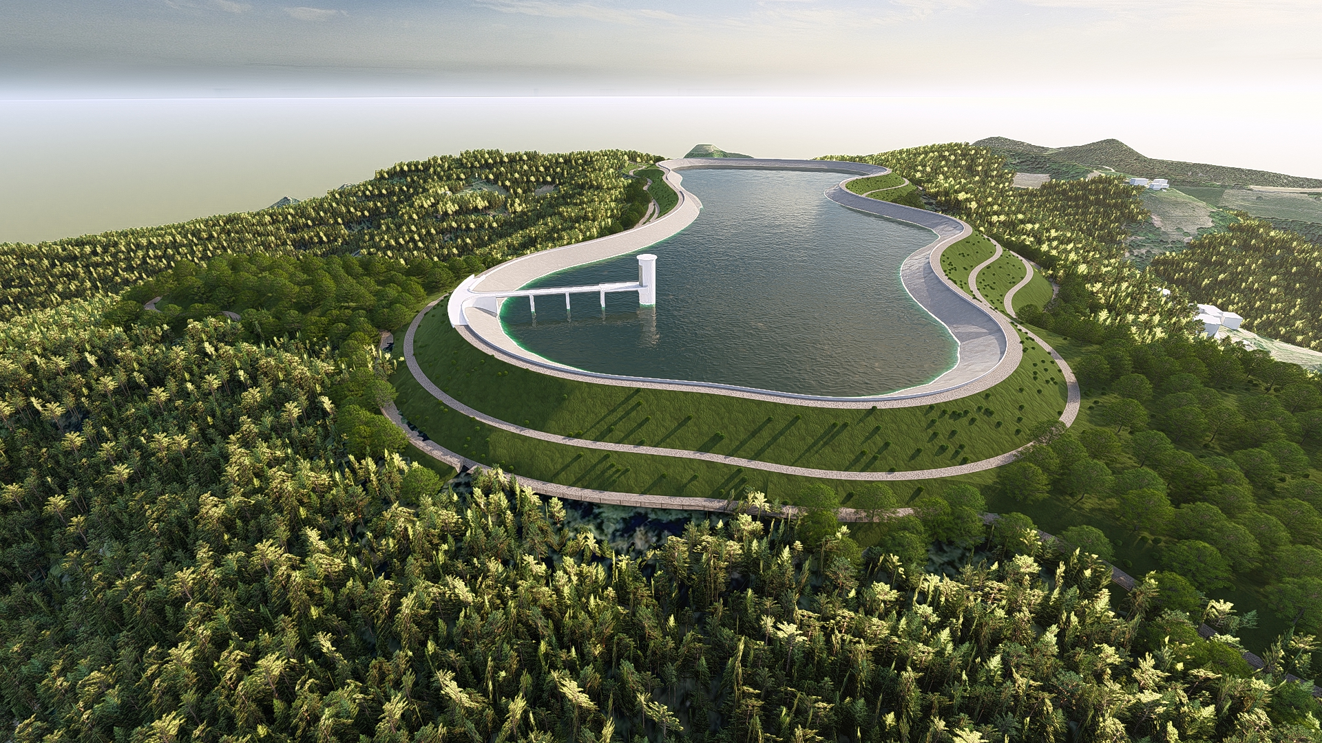
The upper storage basin (Figure 2) is foreseen at Kolarjev vrh. The maximum angle of the impoundment is 992 m a.s.l., at which the usable volume is about 3 000 000 m3. The minimum water level angle is 969 m a.s.l., which means that the water level in the basin will fluctuate by 23 m. The head of the power plant will fluctuate between 687.2 m and 711.4 m. The top of the embankment dam of the storage basin will be at 992.50 m a.s.l. and will be additionally elevated on the waterside by a reinforced concrete wall. The inlet-outlet structure will be of a tower design with a cylindrical cross-section. The connection between the top of the embankment dam and the inlet structure is foreseen to be made with a bridge.
 Figure 2: Upper storage basin
 Figure 3: View of the envisaged cavern with the envisaged tunnels and connections
The lower platform (Figure 4) will accommodate the outlet channel of the PSP to the Drava River, the control building, the technological facility (diesel generator, MV switchyard, transformers, batteries, etc.) and the 400 kV GIS switchyard. The plateau will be used to access the main access tunnel (from 286.0 m a.s.l.) and the service tunnel from 302.9 m a.s.l.
 Figure 4: Proposed layout of the lower plateau with associated facilities.
3. CONCSLUSION
The current global circumstances highlight the importance of national energy independence. Given the options available to us, Slovenia is currently betting on solar energy. The sun is a volatile resource and when production exceeds consumption, energy will have to be stored. The Kozjak PSP will play a key role in this case. A significant risk of placing new PSP plants is the lengthy process of placing the facilities in the environment. On average, it takes 5-8 years to place new large-scale production units in the environment before a building permit is granted, which is an extremely long period of time. The challenge is, of course, the dispersed population of Slovenia and the placement of new units.
Pumped storage hydropower plants are a technologically proven and economically advantageous way of storing energy. It is essential to stimulate the construction of larger storage facilities in order to ensure the stability of the EE supply. Investments and research into new sites should start immediately, as the placing process is very time-consuming. For a successful transition to sustainable energy, we need to be determined and united in our efforts towards a carbon-free future.
The project is included on the PCI list (Project of Common Interest) within the framework of ENTSO-E for Storage projects.


